|
Evolution of Pratt & Whitney's cryogenic
rocket engine RL-10
|
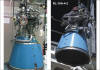
Common elements of all the RL-10 engine models
are the use of liquid hydrogen and liquid oxygen propellants and the expander
cycle. In this cycle, the liquid hydrogen fuel is routed from the pump discharge
to the combustion chamber/primary nozzle (thrust chamber), where it is used
to cool the thrust chamber jacket. The fuel is then directed to the turbine,
where the heat absorbed by the jacket drives the turbine, which is directly
attached to the fuel pump rotor. A reduction gear arrangement drives the liquid
oxygen pump.
The basis of the RL-10 can be traced to work begun by P&W in mid-1956. Under
the auspices of an Advanced Research Projects Agency (ARPA) contract, P&W
began work on a liquid hydrogen powered turbojet engine, designated
as Model 304.
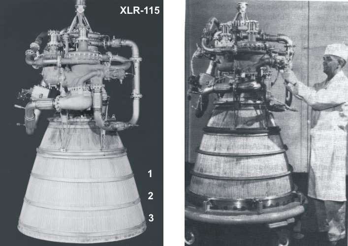
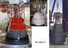
Design of the XLR-115, as the RL-10 was
designated at the time, began in October 1958. The basic configuration of
the engine was established early in the program, and remains consistent through
the present time. Key mechanical features of the configuration include:
• Two-stage centrifugal fuel turbopump with closecoupled inducer
• Single-stage centrifugal oxidizer pump with close-coupled inducer
• Two-stage axial flow turbine on the fuel pump shaft
• Reduction gear system to drive the oxidizer pump from the fuel pump shaft
and synchronize the pumps
• Tubular stainless steel combustion chamber/primary nozzle (thrust chamber)
Early development activities focused on the transition of the expander cycle
technology demonstrated in the modified turbojet configuration of Model 304
to a true rocket configuration. Some of the challenges to be overcome were
of a mechanical nature, such as establishing a viable method of manufacturing
the tubular thrust chamber that forms the core of the expander cycle engine.
In the RL-10 configuration, 360 thin-wall tubes are formed and flattened (spanked)
to form the primary nozzle. One-hundred and eighty of these extend forward
to form the throat and the combustion section of the thrust chamber. The forming
operation must be precise enough so that each tube will fill 1 degree of arc
at the primary nozzle (or 2 degrees at the throat and combustion chamber)
for any point along the varying diameter of the thrust chamber. The spanking
operation must be so precise that all tubes will be in intimate contact with
their adjacent tubes along their entire length to ensure that the manufacturing
process will bond them reliably, while at the same time not crush the tubes
and block the coolant flow. At the throat, the total width of a single tube
is nominally 0.044 in.; therefore, a 0.001 in. deviation from nominal on each
tube could result in a total deviation in the stack-up equivalent to 4 tube
widths. Obviously, establishing a manufacturing method to produce these precise
components repeatedly required extensive development activity. At the same
time, a design code that would predict the thermodynamic characteristics of
the thrust chamber, a critical parameter in the expander engine cycle balance,
had to be developed and refined.
At the time, other issues to be addressed related to component or system interactions
that could not be identified in the Model 304 engine. For example, the 15,000
Ib thrust level of the RL-10A-1 was derived
from the application of the centrifugal hydrogen turbopump used in the Model
304. However, the lightweight turbopump created for the RL-10 accelerated
at a much faster rate than anticipated. This necessitated the development
of a bleed system on the pump to prevent pump stall, and a bypass system on
the turbine to limit turbopump speed and engine thrust overshoot.
In addition to overcoming the specific design challenges inherent with a new
configuration of a high-performance machine, the use of liquid hydrogen fuel
imposed additional challenges in terms of material selection, sealing techniques,
and test and handling procedures.
Liquid hydrogen poses temperature compatibility problems with both metallic
and nonmetallic materials (because of the loss of ductility) and chemical
compatibility problems such as hydrogen embrittlement.
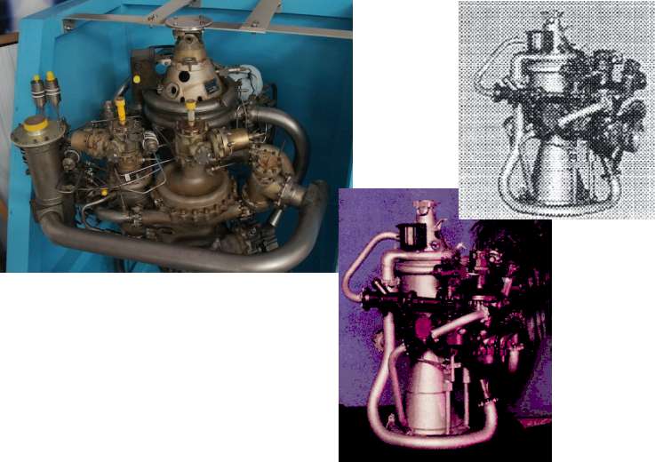
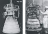
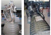
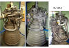
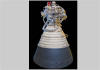
The first experimental engine, shown in Figure 3, was tested in July 1959.
Although the engine achieved ignition during this first test, higher than
predicted turbopump acceleration forced an early termination of the test.
Despite the runaway acceleration (which peaked at a level 50 percent higher
than expected, the robustness of the design allowed the engine to be rebuilt
with only a change of the turbine rotor. Development proceeded at such a high
rate that the program had accumulated over 100,000 sec of component and engine
test time by the end of 1959.
The engine designation was changed to RL-10 in early 1961 after NASA-Marshall
Space Flight Center (MSFC) took over management of the program. The first
production model, the RL-10A-1, completed its preliminary flight rating testing
in November of 1961, thus becoming the first liquid hydrogen engine to be
flightrated.
Two RL-l0A-l flew on the first Atlas/Centaur
vehicle (AC-1). AC-l's mission marked the only flight of the RL-10A-l because
development of a new model, the RL-10A-3 was already underway.
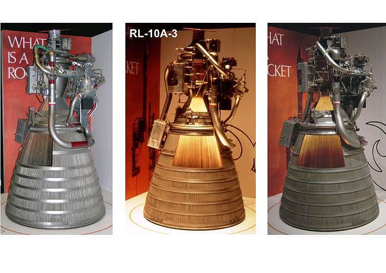
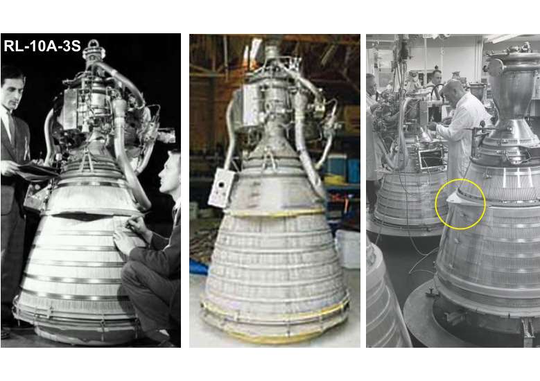
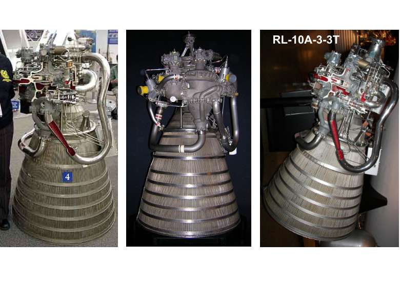
The RL-10A-3 model incorporated fast-opening
chilldown valves to allow better control of the shutdown transient, and improved
oxidizer pump suction capability. This model was used, with minor variations,
on the Centaur and in a six-engine cluster on the Saturn S-IV. (The Saturn
version was designated RL-10A-3S.) Externally,
the RL-10A-3 was virtually indistinguishable from the RL-10A-l. Aside from
the differences previously listed, the main functional difference from the
A-l model was an increase of 5 sec (to 427) in specific impulse.
The quest for higher impulse efficiency continued with the introduction of
the RL-10A-3-1. The injector was modified
for improved combustion efficiency, andsteady-state propellant use reduction
(as a result of improved seals and reduced gearbox coolant flow) raised specific
impulse to 431 sec. As in previous modifications to the basic engine, thnist
chamber geometry, chamber pressure, and thrust were unchanged from the A-l
model.
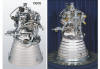
The next variation brought about the first change to the thrust chamber geometry
since the A-l. For the RL-10A-3-3 model,
the throat diameter was decreased, while maintaining the same inlet and exit
diameters. In addition, the fuel turbopump impellers and turbine were redesigned
for higher efficiency. An accompanying increase in chamber pressure raised
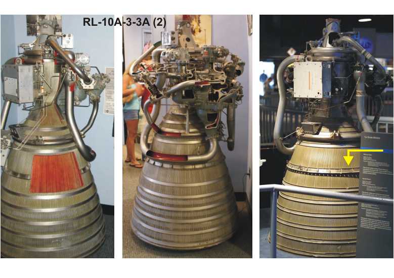
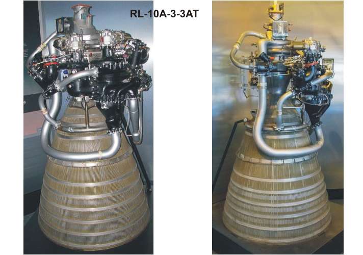
specific impulse to 442 sec. A final refinement to the RL-10A-3 model was
the RL-10A-3-3A. In this configuration,
the throat diameter was once again reduced, resulting in a higher expansion
ratio. Chamber pressure was also increased, resulting in the first uprating
of engine thrust (to 16,500 Ib) since the RL-10A-l. The RL-10A-3-3A flew in
the Atlas/Centaur, and is still in limited production for the Titan/Centaur
vehicle.
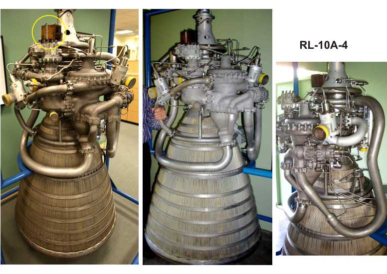
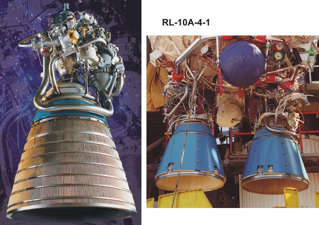
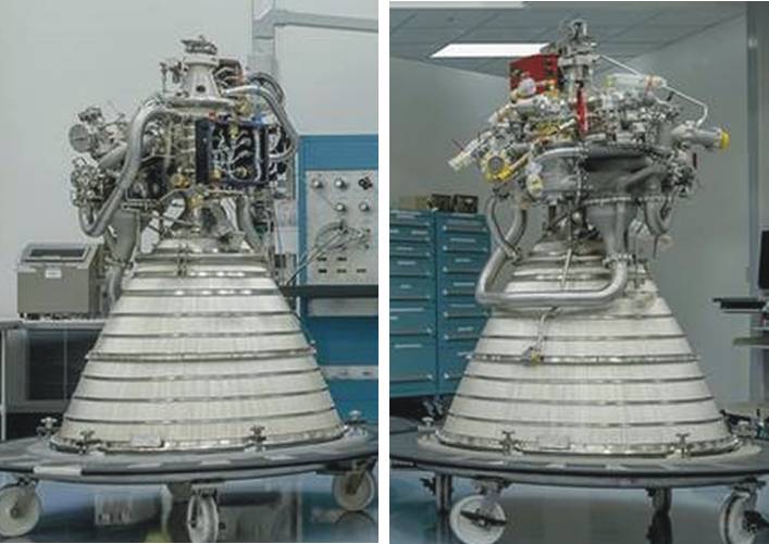
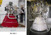
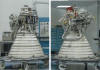
The first major upgrade to the RL-10 family was embodied in the
RL-10A-4 engine. Vacuum thrust was upgraded
from 16,500 to 20,800 Ib (a derating of its 22,000 Ib design point) with changes
to the thrust chamber, upgrading of the turbomachinery, and the addition of
an extendible nozzle. Specifically, the combustion chamber and primary nozzle
geometry changes that had been effected in the RL-10A-3-3A with the addition
of a silver insert at the throat were incorporated into the basic shape of
the tubular chamber. The liquid oxygen pump was completely redesigned, and
other revisions to the turbomachinery provided the required increase in propellant
flow and chamber pressure. Other engine components were redesigned for compatibility
with the increased internal operating pressures. Finally, an extendible, radiation-cooled
columbium nozzle was incorporated, bringing the expansion ratio to 84:1. The
first production engines were delivered in June 1991. A variation of this
model, the RL-10A-4-1 featuring a redesigned
injector for increased performance and using the full design capability of
its components to achieve a thrust rating of 22,300 Ib, first flew in January
1995.
Source: Jorge R. Santiago
Pratt & Whitney, West Palm Beach, FL
AIAA, ASME, SAE, and ASEE, Joint Propulsion Conference and Exhibit, 32nd,
Lake Buena Vista, FL, July 1-3, 1996
|
Variant
|
Nozzles |
Operational Vehicles
|
Engine Parameter
|
|
Oxidizer
Ratio
|
Total
Length
|
Nozzle
Length
|
Throat
Diameter
|
Nozzle max
Diameter
|
=Area
Exp. Ratio
|
Chamb. Press.
(MPa)
|
Thrust
in kN (vac)
|
Spez. Imp.
(sec)
|
|
XRL-115 (RL-10)
|
1 |
Experimental
|
|
5.00
|
|
|
|
|
|
|
|
|
|
RL-10A-1
|
2 |
Atlas SLV3C
|
Centaur A
|
|
|
|
|
40 |
2.07
|
131.2 |
422 |
|
RL-10A-3
|
2 |
Atlas SLV3C
|
Centaur B
|
67.5"
|
34.6"
|
6.1" |
38.7" |
40 |
2.07
|
133.4 |
427 |
|
RL-10A-3S
|
6 |
Saturn-I
|
S-4
|
400.3 |
431 |
|
RL-10A-3-1
|
2 |
Atlas SLV3C
|
Centaur C
|
136.1 |
433 |
|
RL-10A-3-3
|
2 |
Atlas SLV3C
|
Centaur D
|
70.1"
|
37.2"
|
5.1"
|
39.5" |
61 |
2.72 |
140.1 |
442.2 |
|
RL-10A-3-3
|
2 |
Atlas SLV3D
|
Centaur D-1A
|
|
RL-10A-3-3T
|
2 |
Titan-3E
|
Centaur D-1T
|
|
RL-10A-3-3A
|
2 |
Atlas SLV3D, Atlas-G
|
Centaur D-1AR
|
70.1" |
37.2 |
5.1" |
39.5" |
61 |
3.28 |
146.8 |
444.4 |
|
RL-10A-3-3A
|
2 |
Atlas I
|
Centaur D-1B
|
|
RL-10A-3-3AT
|
2 |
Titan-IVA
|
Centaur T
|
|
RL-10A-3-3A
|
2 |
Space Shuttle
|
Centaur G
|
|
RL-10A-3-3A
|
2 |
Space Shuttle
|
Centaur G-Prime
|
|
RL-10A-3-3A
|
2 |
Atlas II
|
Centaur D-2
|
|
RL-10A-4
|
2 |
Atlas-IIA
|
Centaur D-2A
|
5.50 |
70.1" |
37.2 |
5.1" |
39.5" |
61 |
3.98 |
182.4 |
446.4 |
|
RL-10A-4N
|
2 |
Atlas-IIA, Atlas-IIAS
|
Centaur D-2AN
|
90" |
57.1 |
46" |
84 |
185.0 |
448.9 |
|
RL-10A-4-1
|
2 |
Atlas-IIA, Atlas-IIAS
|
Centaur D-2A1
|
70.1" |
37.2" |
39.5" |
61 |
4.20 |
195.7 |
446.4 |
|
RL-10A-4-1T
|
2 |
Titan-IVB
|
Centaur T
|
|
RL-10A-4-1N
|
2 |
Atlas-IIA, Atlas-IIAS
|
Centaur D-2A1N
|
90" |
57.1 |
46" |
84 |
198.4 |
450.5 |
|
RL-10A-4-1N
|
1 |
Atlas-IIIA
|
Centaur D-3A SEC
|
99.2 |
|
RL-10A-4-1
|
1 |
Atlas-IIIB
|
Centaur D-3B SEC
|
70.1" |
37.2 |
39.5" |
61 |
97.8 |
446.4 |
|
RL-10A-4-1N
|
2 |
Atlas-IIIB
|
Centaur D-3B DEC
|
90" |
57.1" |
46" |
84 |
198.4 |
450.5 |
|
RL-10A-4-2
|
1 |
Atlas-V
|
Centaur D-5 SEC
|
70.1" |
37.2" |
39.5" |
61 |
97.9 |
446.4 |
|
RL-10A-4-2N
|
1 |
Atlas-V
|
Centaur D-5 SEC
|
90" |
57.1 |
46" |
84 |
99.2 |
451.0 |
|
RL-10A-5
|
4 |
Delta Clipper DC-X
|
? |
? |
? |
? |
? |
4.3 |
3.98
|
259.0 |
368.0 |
|
RL-10B-2
|
1 |
Delta III
|
DCSS
|
5.88 |
163.5" |
|
5.0" |
84.1" |
285 |
4.36 |
109.4 |
462.4 |
|
RL-10B-2-1
|
1 |
Delta IV
|
DCSS
|
4.44 |
111.2 |
465.5 |
|
RL-10C-1
|
1 |
Atlas V
|
Centaur D-5 SEC
|
5.50 |
86.3 |
|
5.0" |
56.9 |
130 |
? |
101.9
|
449.7
|
|
RL-10C-1
|
2 |
Atlas V
|
Centaur D-5 DEC
|
203.7
|
449.7
|
|
RL-10C-1-1
|
1 |
Vulcan (former)
|
Centaur D-5
|
96.7" |
|
5.0" |
62" |
155 |
? |
105.9
|
453.8
|
|
RL-10C-2
|
1 |
Delta IV
|
DCSS
|
5.88 |
163.5" |
|
5.0" |
84.1" |
285 |
4.44 |
111.2
|
465.5
|
|
RL-10C-3
|
1 |
SLS
|
|
5.70 |
124.9" |
|
5.0 |
73.5" |
215 |
? |
108.5 |
460.1 |
|
RL-10C-5-1
|
1 |
OmegA |
|
5.50 |
96.7" |
|
5.0 |
62" |
155 |
? |
105.9 |
453.8 |
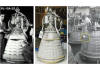
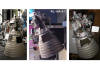
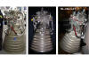
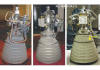
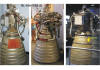
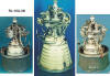
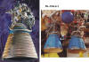
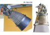
An attempt to sort the mostly
not specified images of the RL-10 variants
|
|
|
|
|

|
|
|
|
|
|
XLR-115 (RL-10)
|
RL-10A-1
|
RL-10A-3
|
RL-10A-3S (Saturn-I)
|
RL-10A-3-1
|
RL-10A-3-3
|
RL-10A-3-3T (Titan3E)
|
|
|
|

|
|
|
 |
similar RL-10A-4-1
|
|
RL-10A-3-3A (1)
|
RL-10A-3-3A (2)
|
RL-10A-3-3AT (Titan4A)
|
RL-10A-4
|
RL-10A-4N
|
RL-10A-4-1 |
RL-10A-4-1T (Titan4B) |
|

|
|


|
|
? |
|
RL-10A-4-1N |
RL-10A-4-2
|
RL-10C-1 (SEC &
DEC)
|
RL-10C-1-1 (Vulcan)
|
RL-10C-X (Vulcan)
|
|
|
|
similar RL-10B-2-1
|
|
|
|
|
|
RL-10B-2 (DeltaIII)
|
RL-10B-2-1 (DeltaIV)
|
RL-10C-2 (DeltaIV)
|
RL-10C-3 (SLS) |
RL-10C-5-1 (OmegA) |
CECE
(DT-Demonstrator)
|
RL-10A-5 (DC-X)
|
The Atlas IIIA and IIIB vehicles use the RL-10A-4-1
engine version. This engine incorporates Direct Spark Ignition (DSI) and helium
ground chilldown features, providing improved reliability and increased performance.
The Atlas V vehicles use the RL-10A-4-2 engine. The
RL-10A-4-2 engine has the benefits of the RL-10A-4-1 engine,
and also incorporates several new features that improve engine reliability
and performance. Several significant operational features are incorporated
into the RL-10A-4-1 and RL-10A-4-2 engines. Before launch, a gaseous helium
chilldown of the LH2 and LO2 turbopumps is performed. During the boost phase,
a pre-chill of the LH2 turbopump is accomplished by flushing LH2 through the
engine and overboard. Both of these operations reduce the amount of propellants
that are used immediately before main engine start and the associated wait
time after separation, and consequently increase performance. These features
were proven out on the first Atlas IIIA, IIIB, and V launches. Another improvement
for the RL-10A-4-2 engine was the addition of a fourth solenoid valve with
plumbing that allowed for independent control of the OFCV bypass. This enables
trickle cooldown of the engine before second or third engine starts for increased
vehicle performance.
The most significant change that is part of the RL-10A-4-2 engine is the incorporation
of Dual Direct Spark Ignition (DDSI) system. The DDSI is a fully redundant
electronic ignition system that has been fully qualified at the component
and system level to the more severe Atlas V environments.
The change to a new booster for the Atlas V program provided an opportunity
to pre-deploy or fix the Centaur engine nozzle extension before launch. The
Atlas II and III families use a deployable nozzle extension that must be actuated
just before main engine start. The Atlas V vehicles, all using the RL-10A-4-2
engine, have sufficient space in the interstage area to allow the nozzle to
be fixed, consequently removing a critical event from the flight sequence,
improving reliability and performance. The RL-10A-4-2 engine can accommodate
either the existing extendible nozzle extension or a fixed nozzle extension.
The engine is gimbaled during flight by using two different flight-proven
systems. EMAs for thrust vector control were developed for the SEC program
and are used on all single-engine Common Centaurs.
Dual-engine Common Centaurs use the hydraulic thrust vector control system
that has been used on all previous Centaurs.
Source: Thomas J. Rudman & Kurt L. Austad
Lockheed Martin, Space Systems Company, Denver, Colorado USA
4th International Conference on Launcher Technology; December 2002 – Liege
(Belgium)
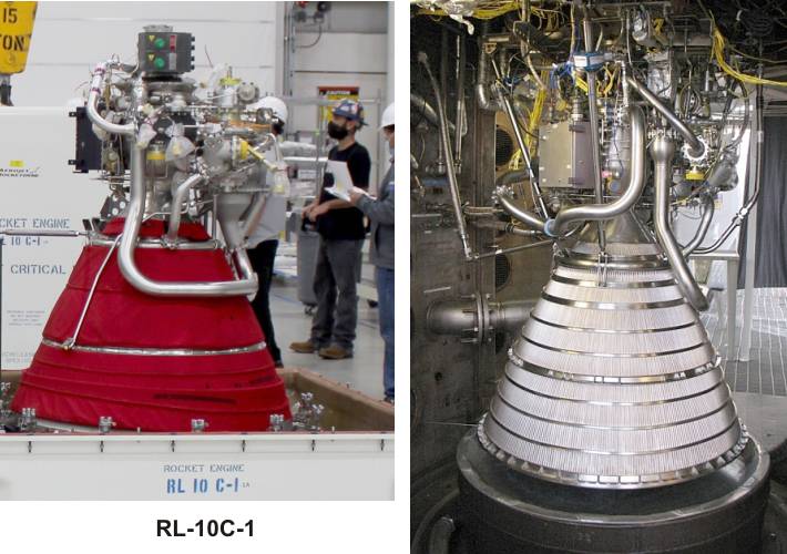
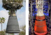
The new powerplant
RL-10C-1 is making its first flight in December 2014.
The RL-10C blends the configurations of the RL-10A-4 engine from Atlas and
the RL-10B-2 engine currently used to power the Delta IV.
The noticeable change on the RL-10C is a shortened (however fixed ?) version
of the carbon-carbon nozzle extension used by Delta. Other mods include avionics
for active propellant mixture ratio control, a capability currently on the
Atlas RL-10A engines but not on the Delta’s RL-10B version and a redundant
dual direct spark ignition system that was standard on the Atlas. The turbomachinery
configuration on the RL-10C is common with the RL-10A, but the RL-10C adopts
the chamber and injector configuration from the RL-10B.
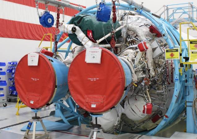
The RL-10C-2 engine uses similar chamber
and nozzle configuration as the RL-10B-2 engine currently used on Delta. The
RL-10C-2 engine will incorporate all improvements from the RL-10C-1, including
an upgraded redundant ignition system to improve reliability, changes to the
engine plumbing to improve starting operations, a propellant valve design
update, and a number of improvements including a revised gear train
and seal improvements. Additionally, the RL-10C-2 is intended to be qualified
to operate with active Mixture Ratio control, a capability available on Atlas/Centaur
missions dating back to 1965. This feature, enabled on Delta IV by the addition
of Common Avionics. The RL-10C-2 will continue to use the 3-segment extendible
nozzle currently used on the RL-10B-2. The RL-10C-2 will look virtually the
same as an RL-10B-2.
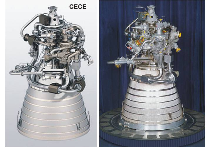
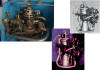
The Common Extensible Cryogenic Engine (CECE)
is a testbed to develop RL-10 engines that throttle well. NASA has contracted
with Pratt & Whitney to develop the CECE demonstrator engine. In 2007 its
operability (with some "chugging") was demonstrated at 11-to-1 throttle ratios.
In 2009 NASA reported successfully throttling from 104 percent thrust to eight
percent thrust, a record for an engine of this type. Chugging was eliminated
by injector and propellant feed system modifications that control the pressure,
temperature and flow of propellants.
|